Saturday, February 26, 2011
Where to Mount the Indicator
I have a small plastic pod from Old Air that was for mounting A/C controls, but I am adapting it to hold the indicator. At first I wanted to try putting LEDs behind the original quadrant. I had a pretty cool setup for mounting the LEDs, but when I tested it out, the LEDs weren't bright enough. And, no way to dim them for night use if you got them bright enough for day use. So, kinda stuck there. Will just use the DD indicator. It will mount under the lip of the dash under the glove box.
Thursday, February 24, 2011
Good News! (I hope)
I got an email from Dakota Digital that should help with my gear shift indicator:
So that's good news. I'm shipping it out via two-day FedEx to them today.
Our engineer made a minor update to the software code. This will now support a PNOD1R or PND21R pattern. You still have to make your false Park to start programming.
We can update that GSS of yours for no charge if you send that to us.
So that's good news. I'm shipping it out via two-day FedEx to them today.
Sunday, February 20, 2011
Backup Plans
So today I went to the hardware store and bought a small sheet of brass, some brass screws, some epoxy, and a countersink.
I had already removed the original contacts and used the Dremel to smooth the inner face. I countersunk a hole that was already in the shell for one of the removed terminals.


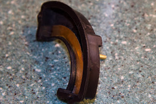
I had already removed the original contacts and used the Dremel to smooth the inner face. I countersunk a hole that was already in the shell for one of the removed terminals.

I cut a small piece of the brass sheet to work with, and using the grinder and smaller tools I made a brass arc that fits the smaller radius of the switch case. Then I attached a "terminal" by soldering a screw to the back of the arc. That was fun. I had a heavy steel plate I set on the stove. Then I set the arc on the plate and the screw in the approximate position to line up with the terminal hole in the shell. Turned the stove burner on and then melted a little pool of solder around and under the screw head on the arc. I could nudge the arc off the edge of the plate and carefully pick it up with pliers and let it cool. Then insert it into the shell to see if the terminal lined up with the hole. It took three tries to get it right.

The arc isn't perfect, but it fits well enough. It doesn't need to be perfect, just has to stay in contact with the bottom half of the slider.

Here you can kind of see how the terminal goes through the shell and out the back. This was a test fit before I epoxied it in.

I used epoxy so the brass strip would not flex and stress the solder joint with the terminal. I put a nut on the back side of the terminal and snugged it. It can stay there and I'll have securing nuts on each of the screw terminal contacts. An outer nut will hold the attached wire to the indicator and relays.
Saturday, February 19, 2011
No Good
Well, fooling the programmable gear indicator box with a false Park (the P is programmed into the box in a spot that is beyond the mechanical limits of the linkage, making it a position that is never used) does give a consistent Neutral indication. But it does not solve the fact that the box expects the sequence P-R-N-O-D-2-1, P-R-N-D-2-1, or P-R-N-D-1 (L). If I move the sensor past where 1 would normally be to make a false Park (so N-O-D-1-R-P), then when I go to program the Overdrive position, it just keeps flashing. Clearly it sees the value from the sensor as unacceptable. If I do a false Park at the other end (so P-N-O-D-1-R), my results stored in the box end up being (P-)N-D-D-D-R. Nothing I can do will get it to indicate the O or the 2 unless I program the positions in the traditional modern PRNOD21 pattern.
So, I have to decide if this is acceptable... which I don't think it is... or if I want to pay $$$ for a custom firmware job... or look for/make something else.
I still have in the back of my mind to make over the Chevy column mounted safety/backup switch and I have removed the internal contact in preparation to start seriously working on converting it. Now that I have the digital gear position display, I don't have to use it with the sensor and brain. I can hard-wire any custom solution I come up with to the indicator and to backup/start relays. What I need is a strip of brass I can machine to fit the inside curve of the switch case, then some brass flush-mount screws to mount on the outer curve of the case. One for each gear position... maybe a few for reverse. Then I just need to mark off the positions, drill the holes for the screws and make a terminal for the common brass strip.
Monday, February 14, 2011
Where the Rubber Meets the Road
I called Diamondback Classics today and placed my order for 4 new tires for the Chief. 215/75R15 with 2-5/8" wide white walls. I will mount them on my '76 Buick OEM steel wheels which I modified to fit and which will work with my hub caps that I want to keep. $214 * 4 + $117 to ship = $973.00. Well, I had to buy something with part of my tax return. :-)
I also talked (via email) with the folks at Dakota Digital today. It turns out to be exactly what I thought.
I also talked (via email) with the folks at Dakota Digital today. It turns out to be exactly what I thought.
"While you can eliminate both Overdrive and 2nd gears through double tapping, you cannot merge Park and Neutral."As I explained to DD, one of the brainwaves from last night was to disconnect the sensor and move it forward a bit to where a theoretical "Park" might be if my transmission had one. I could set that, then reconnect the sensor linkage and go through the rest of the positions. With the sensor connected, the sensor will never be able to hit "Park" but that doesn't matter, as I have no Park and I don't want it ever to be displayed. I DO want the safety switch to let me start only in Neutral through. And I also want the backup lights to come on at the right time. Dakota Digital thought that might just do it.
"Fooling it into a false Park position could make it work for programming."So next chance I get (hopefully this Saturday) I will give this a try. I hope it works out as I like the setup. I need to figure out where I am going to mount the indicator too. I don't want to cut any holes.
Sunday, February 13, 2011
Frustration
Spend part of yesterday and most of today screwing around with the shift position indicator stuff.
I bought the GSS-2000 because I have a dual-range Hydramatic. Instead of the PRNDL/PRND12/PRNOD21 type pattern, my pattern is N, D-High, D-Low, L, R. I can not get the silly controller to completely be OK with that. If I program it as if each detente were the modern pattern, it works fine. So the position pot is detecting the correct locations. But the brain box gets flummoxed if I try to program it with Either N D 2 1 R or N O D 1 R. I can get it to recognize either N or P, and I can make that always N on the display. And I can get R to reliably be indicated, so I will be able to get the safety relay and the backup lights working, but the brain refuses to recognize 2. It treats both D ranges as D, no matter what I do, and sometimes wants to get Low as 1 and sometimes as a D also. sent a note to Dakota Digital to see if they had any suggestions. I bought this rig because it promised to be fully programmable regardless of the position of the pot sender. It seems to be only partially true.
I spent a lot of time screwing around with sensor position, arm length, etc., before I realized it's an electronic issue, not a mechanical one. I want to put the longer arm back on and the shorter linkage. Then, I want to try something I thought of since I came in and showered. Once I have the longer arm and thus, more room to sweep the sensor I want to try positioning the arm outside of the mechanical reach of my shifter to simulate Park. Then I will reconnect the linkage and program the rest of the positions. Maybe that will do the trick. The shifter will stop at Neutral, and never reach Park, but at least I won't be boggling it's brain by having N and P in the same position. That'll have to wait for next weekend, I'm afraid. I need to think about ordering tires this week.
What's left to do?
- Screw around some more with the shift position sender (working on this now).
- Program the shift position decoder.
- Permanantly attach and wire the shift position decoder, incl wiring to safety relay and backup lights.
- Put in shift position indicator. (Where?)
- Get new tires.
- Enjoy the car!
Saturday, February 12, 2011
Test Drive!
Put the front tires on and adjusted approximate toe-in, then carefully pulled the car out of the garage. Bled the rear brakes and re-bled the fronts just to be sure. Replaced the brake light switch and wired it up. Then it was time to test drive. The wheel centering seemed good. No pulling. There is more brake pedal travel before anything happens on this car compared to the '58 Cad.
Back at home I adjusted the pedal height a bit, then tightened down the clevis pin on the brake pedal. I had forgotten to remove the bleeder tool from the combo valve so I did that too, then went out for a second around the block spin. Did a few 30 to 0 stops with no trouble. Tried a U-turn to see how the turning radius was impacted. It has been, a little. I'm thinking I might want to order the longer Chevy steering arms to see if they would fit.
After the second drive I:
- Put the glove box light in (with LED bulb).
- Put the glove box back in the dash.
- Put the horn button back together and tightened down the steering wheel.
Friday, February 11, 2011
Sway End 2
The sway bar end kit I got from Rock was for one end. That's why I ordered a second kit. Same part number, same price. The kit I got from Amazon had complete parts for both ends. So now I have parts for one spare end. Sheesh! But I need to get the rubbers for where the bar mounts to the frame now... later. Other than that, the sway bar is done. I also got a fine selection of hardened washers from McMaster to secure the tie rod ends to the steering arms. So that's done.
Sunday, February 6, 2011
Shocks and One Sway Bar End
Hmmm... When they say sway bar link kit, they don't always mean it does one sway bar (two ends). Sometimes they mean a kit for one end. So I was only able to do the driver's side today. A second kit is on it's way. But I did get both new front shocks in. the towers on top were bent out of shape, especially the right one. I straightened them, made sure I kept 4" on center mounting hole positioning, and I welded a brace on one side to help them keep their shape. I can't imagine what bent them forward.


So then I was going to secure the tie rod ends but found that the '69 Camaro ball stud has a longer taper than the '55 Pontiac steering arm wants. I think a couple of hardened washers will do the trick here, but I'm fresh out. Ordered some from McMaster and I'll deal with it next weekend along with the other sway bar link.

I worked pretty hard yesterday so I'm taking it easier today. Not looking forward to the Dentist visit tomorrow.
Saturday, February 5, 2011
Getting Things Done!
Exhaust system modifications for steering: Labyrinthine left leg lengthening completed and welded up, gasket replaced, 2" stainless lap clamp at joint, Done!
Power steering system: Mount modifications completed, pump installed, Gates 7480 belt installed, reservoir mounted, hoses installed, filled, bled, functional, no leaks, Done!
Started the engine. We have power to the brakes, power to the steering, heat to the underseat register. Best of all, the engine is QUIET now with the new damper.
 |
| Did you ever see such a crazy pipe? |
 |
| They look even but the left pipe really hangs lower than the right. Always has, even before I lengthened it. |
Power steering system: Mount modifications completed, pump installed, Gates 7480 belt installed, reservoir mounted, hoses installed, filled, bled, functional, no leaks, Done!
 |
| Heavy angle plus parts from the Flaming River Chevy mount. |
 |
| The turnbuckle is a very tight fit and barely clears the alternator belt. |
 |
| Hoses routed. I don't much care for this type of hose, but it seems durable. |
 |
| Pump, hoses and reservoir (next to the radiator). |
Started the engine. We have power to the brakes, power to the steering, heat to the underseat register. Best of all, the engine is QUIET now with the new damper.
Subscribe to:
Posts (Atom)