Wednesday, December 28, 2011
Title Released
Awhile back I paid off the loan on this car and they sent me the released title. I took it over to AAA today and submitted it for a new title sans lien holder since I had to get some notarizations done anyway. Should arrive in a couple of weeks.
Saturday, September 17, 2011
Front Wheel Bearings
Today I took a shot at tightening the two front wheel bearings. They were indeed too loose, especially the right side. I thought I might have to take the outer bearing apart and cut down the sleeve insert that came with the disc brake kit, but I just needed to tighten them very tight and them back them off a bit. The right may still be a bit tight, but I will let it ride for now.
Started to measure for the adjustment to the rack so it will end up more or less level and centered. It needs to come over to the right about 1/2-3/4 inch so I will need to shim the left side out. I'm still not sure how I want to proceed with the worm gear steering, but it's here if I want to go to it. I'll adjust this and see how I feel about it.
Started to measure for the adjustment to the rack so it will end up more or less level and centered. It needs to come over to the right about 1/2-3/4 inch so I will need to shim the left side out. I'm still not sure how I want to proceed with the worm gear steering, but it's here if I want to go to it. I'll adjust this and see how I feel about it.
Monday, September 5, 2011
Steering Redux?
So I need to do some fixup work on the steering, since I did not get the rack mounted level. Starting to think about doing that now. The weather is still too hot but it seems like I've gotten lazy and I want to get back into the cars. The rack and pinion system is nice in some ways but I am unhappy with it in others... for example, the rack seems to fight back just a tad when you turn the wheel very suddenly. Almost like the fluid on the one side of the ram can't get out of the way of the pressurized side of the ram fast enough. I can't say I've ever experienced that on the '49er's rack. Then there is the issue of turning radius... or the lack of it since the rack went in. With the '49er, the kit came with replacement steering arms. This rack was supposed to not need them, but that would have been while using the rack on the car it was designed for, which is not this Pontiac.
Thinking I might want to return to a conventional worm gear box... I just happen to have the one I started to prep for this car sitting out in the back garage. I'd need a set of tie rod ends and maybe an idler arm... or maybe not. I'd have to look over the original parts to see if they are at all worn or damaged. The car is low mileage but these parts are not expensive, so maybe I should just replace them anyway. Either way, I would retain the Flaming River pump and steering column. I can just sell the rack and it's cradle, or park it on a shelf.
Hmmmm...
Saturday, August 13, 2011
Radiator Picked Up & Put In
Well, I think I'm kinda impressed with Burbank Radiator, only cost be $150 to have them rod out the tubes, re-solder the tanks and put a new overflow tube on it. They sprayed a little fresh paint on it and pointed out how the original radiators have the year stamped on the tank. Hadn't noticed that before! I got a new 7lb cap from CPR and I'll be leaving the recovery bottle off.
Bolting the unit back in place was easy. I used a new piece of heater hose to connect the bottom of the radiator to the heater return. Hoses and fan shroud all in back in place. Filled with 3-1/2 gallons of Prestone and voila! No leaks. Good as new and cheap too. Doesn't get any better than that.
Bolting the unit back in place was easy. I used a new piece of heater hose to connect the bottom of the radiator to the heater return. Hoses and fan shroud all in back in place. Filled with 3-1/2 gallons of Prestone and voila! No leaks. Good as new and cheap too. Doesn't get any better than that.
Tuesday, August 9, 2011
Radiator Drop-off
Dropped the radiator off at Burbank Radiator this morning. I was expecting the guy to just write up a re-core for me. But instead, he showed me how this type of radiator is constructed and advised me that it would be better if he rebuilt it with the existing core if it was still sound. He would just rod it out and resolder it, then pressure test it. He will also replace the overflow tube. I had said I wanted to have the tube modified to use a recovery tank but he said this is not advised for this type of radiator. He says it's a low-pressure design and using a closed system tank will cause the upper radiator tank to swell and the solder seams to stress beyond the design limits.
So I went Googling for some more information and I found a link to the H.A.M.B. that pretty much explained what the Rad shop guy was telling me. The older un-reinforced tanks are designed for low pressure... 7 pounds or so. The tank's inlet and cap have to be designed for recovery and that generally means a higher pressure cap if you want recovery to work properly. Otherwise it will not really pull the coolant back in and you're kinda wasting your time, not to mention stressing the system needlessly.
So, score one point for the Radiator Man... His name is Steve and he seems AOK to me so far.

Sunday, August 7, 2011
Radiator Removal
Drained the cooling system... again. This car gets it's coolant changed every 50 feet. Man, I don't recall where this rad cap came from but it looks super cheesy so I ordered a new one from CPP.
SKU: C850795R
Product: Cap, Radiator, RC1, 1951-56 All exc AC
Quantity: 1
Unitprice: $11.50
Total For Item(s): $11.50
Subtotal: $11.50
Shipping: Not Include in Price
Total Tax: $0.83
Total Cost: $12.33 + shipping
The three bolts on each side of the radiator proved to be fun. The driver's side especially, since there is very little room with the battery and the new power steering pump.


Saturday, August 6, 2011
Started Up...
...And found the radiator is leaking, either from the cap or the overflow tube... not good! Well I've been thinking I needed to get the rad redone anyway. It's original and while it wasn't leaking before, it looked dicey.
I checked my local web pages (Google) and found a link to this place in Burbank that has good feedback.

Will check them out next week. Maybe I'll pull the radiator tomorrow. Not feeling it today.
I checked my local web pages (Google) and found a link to this place in Burbank that has good feedback.

Will check them out next week. Maybe I'll pull the radiator tomorrow. Not feeling it today.
Sunday, May 22, 2011
Price Check
Yes, I'm checking prices on all my cars in case I need to liquidate. I think this would be the very last car I would sell if I had to get rid of any. But here it is:

So it's good to know even at average, which this car is not, it is still worth more than I paid for it. :-)

So it's good to know even at average, which this car is not, it is still worth more than I paid for it. :-)
Wednesday, April 20, 2011
Tyerman's
Alright, I made it to Tyerman's today, finally! I have to say, I am still not 100% comfortable driving this car, and the ride to Tyerman's didn't help. If I hit the brakes hard the right wheel kept screeching like it was going to lock up and the steering is just plain weird feeling to me. All that keeps going through my mind is that I made a terrible mistake doing these things to this car and I should never have started them. But Bob says I always act this way after I've made major changes and before they're all adjusted and I've gotten used to them. Fact is, the ride home with the steering nicely aligned was much better and the screechy right wheel was not really noticable anymore.
But, there really are a couple of issues to attend to. The guy at Tyerman's pointed out that the wheel bearing on the right (and he didn't mention the left but it might be the same) is loose so even with the nut pretty tight, the bearing doesn't snug down like it should. Recall that the outer bearings for this setup are for a 1971-76 Riviera and that to make them fit the Pontiac, the Scarebird kit includes a machined ring that fits into the bearing center.

It may just be that I need to tighten the spindle nut down really, really hard to fully seat that sleeve, then back it off to a comfortable snugness so the bearing doesn't heat. Maybe I didn't do that when I assembled the rotors. I can't remember and I do remember thinking myself that the bearings seemed loose. If that doesn't do the trick, I can contact Scarebird for advice.
The other issue the mechanic found... and I am really embarrased about this one... is that the rack is not mounted level! It is down about a half to three-quarter inch on the right side and while it is functional, it's not right. Recall that this is the side where I had to re-drill the mounting holes to fit the Pontiac idler arm bolt pattern. And I realise now that part of the problem is I measured but I measured from the floor to the rack bottom when the car was on jacks and the jacks were obviously not even. I remember thinking that the thing looked a bit off... but at the shop, being down in their pit, it's very freakin obvious how crooked it is. So... the simplest thing to do is to remove the rack bracket and redrill the holes lower on the right plate. Now, maybe one hole will be one of the ones I didn't think I could use originally... I will have to look once I have the bracket off. I think the rack can stay in the car, and only the lollipop bearing bracket will need to be disconnected.
There is no big hurry to do the rack adjustment, other than my pride and wanting it done right. But the bearing should get attention real soon as it could cause abnormal stress and wear on the spindle.
One step forward, two steps back.
Wednesday, April 6, 2011
False Start
I was going to go over to Tyerman's for an alignment today, but when I pulled the car out of the driveway and began driving, I heard some strange klunking noises from the front wheels, particularly when braking. OK, I know what that is... these calipers are just not fitting inside the wheels properly. I had tried grinding on the calipers a bit and they cleared when I was turning the wheels by hand, but now with the weight of the car and pressure applied to the caliper, it's banging into the four tabs of the wheel center where they attach to the rim.
The good news is I had already ordered a set of spacers from Summit Racing and they've been sitting here waiting for a need to arise. I originally planned them for the '49er. Made by BilletSpecialties they are part number WSG5L375. You guessed it: Wheel Spacer, 5 lug, .375 thick. Done. But now it's 3 PM and I don't feel like trying to get over to Tyerman's this late in the day. I roll up the sidewalk out front at 5 PM. ;-) Another day!
But now that I have it back up on jacks to do the spacers, I got to thinking I wanted to re-visit the steering wheel to rack linkage again. It's not as smooth as it should be which tells me at least one of the joints is being angled too hard. I want to see if I can remedy that. I tore it apart and reworked it. Much smoother now. [Rerouted the starter cable as well.]
Saturday, April 2, 2011
Lube Job
I had ordered some shorter steering arms in an attempt to get some turning radius back, but the Chevy ones won't work and I just decided I don't care enough about it right now to keep the car up on the jacks any longer. So I hooked up my new pneumatic grease gun and greased all the joints on the front suspension and steering, including the new tie rod ends, did some grinding on the calipers for a bit of extra wheel clearance, and bolted on the front wheels with the new tires on them. Then I pulled the car out of the garage and put the glove box door back on and attached the little panel for the shift indicator. I vacuumed the carpet and found there is a worsening tear in the seat on the passenger side. :-(
Need to take a day off to go over to Tyerman's for an alignment now.
Need to take a day off to go over to Tyerman's for an alignment now.
Saturday, March 19, 2011
2 Tires
Got the first two tires mounted today.Took them over to my favorite tire shop, Western Tire in Burbank.I'm not going to put them on the car yet. I ordered a set of steering arms from Eckler to see if I can increase my turning radius a bit. We'll see if they fit. [They do not!]


Sunday, March 13, 2011
Paint Play
Got to mix up a small batch of my new paint I bought last week to spray the little panel I'm putting my shift indicator in. I really like this paint. It's Valspar 327 Series High Solids Acrylic Urethane Enamel. It takes a reducer and a hardener but I just mixed it ad hoc in the pot and sprayed. No problem at all! Dried nice and shiny and I'll let it sit in the garage til next weekend when I will mount the indicator and figure out how I am attaching it to the dash. I love single-stage paint.


Saturday, March 12, 2011
New Wheel
Today was a nice day and a trip to the local wrecking yard seemed like a fine thing to do. I needed one more wheel since one of the four '70's Buick wheels had gotten damaged. I had to hit the ATM to get some cash first, then paid my $2 to gain entry to the yard. I had my big bucket with tools in it along so I could remove the wheel and maybe some other small parts if I found something interesting. Within a few minutes I found a '76 Cadillac which had all four wheels removed and laying nearby. I looked at the two fronts, deciding I'd like to get those two so I had one wheel as a spare. Both tires were flat and shot. I walked to the front of the yard to see if I could find a cart or wheelbarrow, but someone was walking off with the last one just then. So I walked back and grabbed one wheel and tire, and manhandled it with my tool bucket to the checkout windows. It seemed several other folks had wheels/tires in line too. It took forever to get through the line, and when I got to the window, I found out why... If you want a wheel AND a tire, you have to pay for both even if the tire is shot, as was the case with my prize. He said something like $20... EACH! Further inquiry on how to buy just the wheel I needed proved a little frustrating, since he did a poor job of explaining, which is why everyone with wheels and tires in front of me in line had taken so long.
Turns out to be a little scam. To avoid paying $20 for a worthless tire I would have to pay $3.50 in cash, in advance at this window to get a ticket to get the tire breaker station at the yard to remove the tire for me. Then I would have to come back to the window to pay for the wheel, which I think he said was going to be around $20 also. Well, if I took the tire home, I'd just have to pay a disposal fee at the tire dealer, probably about $5, so I'm money ahead... except the $2 I paid to enter the yard makes me $0.50 behind. Then too I gotta lug this heavy buggar over to the breaker and back with my tools. Up to this point I was thinking I would buy the one and take it to my truck, then go get the second... that idea died about here. Wait in line at the breaker, then go back... with just the wheel and tools so the load is lighter now... and stand in line at the window again. Then lug it to the gate and have someone smear red ink pen on the wheel and the receipt, then lug it out to my truck. I was done for the day after that.
The good thing is, I fit the wheel to the front rotor and it fits without scraping anywhere. I compared it to one of the Buick rims and it looks identical. All I lack now is a spare and I think I'll just order a chrome smoothie and get it delivered. Phooey. I think they run about $30 and when you figure the time and hassle, I think I'd pay double that to avoid the wrecking yard experience again.
You know, yards are great. I enjoy the self service ones for small parts I can manage myself. This is the first (and last) time I tried to get large, heavy items myself and I think it is definitely worthwhile to go to a full service yard or order online for those items.
Tuesday, March 8, 2011
Don't (Re)Tread On Me
The new Diamondback Classic tires arrived tonight via UPS. The driver was not at all impressed that I accepted delivery in my boxer shorts but he didn't complain either. Might have to get at least two of them mounted up this weekend.
Monday, March 7, 2011
Dash Paint Mix-up
I had a local paint shop mix me up a quart of single stage paint for the interior metal and trim. Took the glove box door over to them Saturday but it was too late to get it mixed up. They had it ready to go when I stopped by today after work. It needs a reducer and a hardener, so the yield will be over two quarts. More than I need but good to have extra. Looks like the color a good match. Certainly far better than the spray bomb I had made up at that scratch-fix place awhile back. That stuff was so red it was unusable. I did spray it on the kick panels before I put them in but they are semi hidden and not so noticeable.
Saturday, March 5, 2011
Success!!!
I got the brain box back from Dakota Digital this week and finally had a chance to test it today. AND IT WORKS!!! Flawlessly!
Meanwhile, the under-dash housing I'm going to mount the indicator in needs to be painted so I took my glove box door over to the local paint shop to get a quart mixed up to match the dash. They were open but unfortunately I got there too late for them to mix it today. I had to leave the door with them and they will call me Monday.
What's left to do?
- Finish wiring the shift position decoder (safety relay and backup lights need done).
- Paint the housing and mount the shift position indicator.
- Get new tires.(Should arrive next week sometime.)
- Get a 4th rim.
- Get tires mounted on rims.
- Enjoy the car!
Saturday, February 26, 2011
Where to Mount the Indicator
I have a small plastic pod from Old Air that was for mounting A/C controls, but I am adapting it to hold the indicator. At first I wanted to try putting LEDs behind the original quadrant. I had a pretty cool setup for mounting the LEDs, but when I tested it out, the LEDs weren't bright enough. And, no way to dim them for night use if you got them bright enough for day use. So, kinda stuck there. Will just use the DD indicator. It will mount under the lip of the dash under the glove box.
Thursday, February 24, 2011
Good News! (I hope)
I got an email from Dakota Digital that should help with my gear shift indicator:
So that's good news. I'm shipping it out via two-day FedEx to them today.
Our engineer made a minor update to the software code. This will now support a PNOD1R or PND21R pattern. You still have to make your false Park to start programming.
We can update that GSS of yours for no charge if you send that to us.
So that's good news. I'm shipping it out via two-day FedEx to them today.
Sunday, February 20, 2011
Backup Plans
So today I went to the hardware store and bought a small sheet of brass, some brass screws, some epoxy, and a countersink.
I had already removed the original contacts and used the Dremel to smooth the inner face. I countersunk a hole that was already in the shell for one of the removed terminals.


I had already removed the original contacts and used the Dremel to smooth the inner face. I countersunk a hole that was already in the shell for one of the removed terminals.

I cut a small piece of the brass sheet to work with, and using the grinder and smaller tools I made a brass arc that fits the smaller radius of the switch case. Then I attached a "terminal" by soldering a screw to the back of the arc. That was fun. I had a heavy steel plate I set on the stove. Then I set the arc on the plate and the screw in the approximate position to line up with the terminal hole in the shell. Turned the stove burner on and then melted a little pool of solder around and under the screw head on the arc. I could nudge the arc off the edge of the plate and carefully pick it up with pliers and let it cool. Then insert it into the shell to see if the terminal lined up with the hole. It took three tries to get it right.

The arc isn't perfect, but it fits well enough. It doesn't need to be perfect, just has to stay in contact with the bottom half of the slider.

Here you can kind of see how the terminal goes through the shell and out the back. This was a test fit before I epoxied it in.

I used epoxy so the brass strip would not flex and stress the solder joint with the terminal. I put a nut on the back side of the terminal and snugged it. It can stay there and I'll have securing nuts on each of the screw terminal contacts. An outer nut will hold the attached wire to the indicator and relays.
Saturday, February 19, 2011
No Good
Well, fooling the programmable gear indicator box with a false Park (the P is programmed into the box in a spot that is beyond the mechanical limits of the linkage, making it a position that is never used) does give a consistent Neutral indication. But it does not solve the fact that the box expects the sequence P-R-N-O-D-2-1, P-R-N-D-2-1, or P-R-N-D-1 (L). If I move the sensor past where 1 would normally be to make a false Park (so N-O-D-1-R-P), then when I go to program the Overdrive position, it just keeps flashing. Clearly it sees the value from the sensor as unacceptable. If I do a false Park at the other end (so P-N-O-D-1-R), my results stored in the box end up being (P-)N-D-D-D-R. Nothing I can do will get it to indicate the O or the 2 unless I program the positions in the traditional modern PRNOD21 pattern.
So, I have to decide if this is acceptable... which I don't think it is... or if I want to pay $$$ for a custom firmware job... or look for/make something else.
I still have in the back of my mind to make over the Chevy column mounted safety/backup switch and I have removed the internal contact in preparation to start seriously working on converting it. Now that I have the digital gear position display, I don't have to use it with the sensor and brain. I can hard-wire any custom solution I come up with to the indicator and to backup/start relays. What I need is a strip of brass I can machine to fit the inside curve of the switch case, then some brass flush-mount screws to mount on the outer curve of the case. One for each gear position... maybe a few for reverse. Then I just need to mark off the positions, drill the holes for the screws and make a terminal for the common brass strip.
Monday, February 14, 2011
Where the Rubber Meets the Road
I called Diamondback Classics today and placed my order for 4 new tires for the Chief. 215/75R15 with 2-5/8" wide white walls. I will mount them on my '76 Buick OEM steel wheels which I modified to fit and which will work with my hub caps that I want to keep. $214 * 4 + $117 to ship = $973.00. Well, I had to buy something with part of my tax return. :-)
I also talked (via email) with the folks at Dakota Digital today. It turns out to be exactly what I thought.
I also talked (via email) with the folks at Dakota Digital today. It turns out to be exactly what I thought.
"While you can eliminate both Overdrive and 2nd gears through double tapping, you cannot merge Park and Neutral."As I explained to DD, one of the brainwaves from last night was to disconnect the sensor and move it forward a bit to where a theoretical "Park" might be if my transmission had one. I could set that, then reconnect the sensor linkage and go through the rest of the positions. With the sensor connected, the sensor will never be able to hit "Park" but that doesn't matter, as I have no Park and I don't want it ever to be displayed. I DO want the safety switch to let me start only in Neutral through. And I also want the backup lights to come on at the right time. Dakota Digital thought that might just do it.
"Fooling it into a false Park position could make it work for programming."So next chance I get (hopefully this Saturday) I will give this a try. I hope it works out as I like the setup. I need to figure out where I am going to mount the indicator too. I don't want to cut any holes.
Sunday, February 13, 2011
Frustration
Spend part of yesterday and most of today screwing around with the shift position indicator stuff.
I bought the GSS-2000 because I have a dual-range Hydramatic. Instead of the PRNDL/PRND12/PRNOD21 type pattern, my pattern is N, D-High, D-Low, L, R. I can not get the silly controller to completely be OK with that. If I program it as if each detente were the modern pattern, it works fine. So the position pot is detecting the correct locations. But the brain box gets flummoxed if I try to program it with Either N D 2 1 R or N O D 1 R. I can get it to recognize either N or P, and I can make that always N on the display. And I can get R to reliably be indicated, so I will be able to get the safety relay and the backup lights working, but the brain refuses to recognize 2. It treats both D ranges as D, no matter what I do, and sometimes wants to get Low as 1 and sometimes as a D also. sent a note to Dakota Digital to see if they had any suggestions. I bought this rig because it promised to be fully programmable regardless of the position of the pot sender. It seems to be only partially true.
I spent a lot of time screwing around with sensor position, arm length, etc., before I realized it's an electronic issue, not a mechanical one. I want to put the longer arm back on and the shorter linkage. Then, I want to try something I thought of since I came in and showered. Once I have the longer arm and thus, more room to sweep the sensor I want to try positioning the arm outside of the mechanical reach of my shifter to simulate Park. Then I will reconnect the linkage and program the rest of the positions. Maybe that will do the trick. The shifter will stop at Neutral, and never reach Park, but at least I won't be boggling it's brain by having N and P in the same position. That'll have to wait for next weekend, I'm afraid. I need to think about ordering tires this week.
What's left to do?
- Screw around some more with the shift position sender (working on this now).
- Program the shift position decoder.
- Permanantly attach and wire the shift position decoder, incl wiring to safety relay and backup lights.
- Put in shift position indicator. (Where?)
- Get new tires.
- Enjoy the car!
Saturday, February 12, 2011
Test Drive!
Put the front tires on and adjusted approximate toe-in, then carefully pulled the car out of the garage. Bled the rear brakes and re-bled the fronts just to be sure. Replaced the brake light switch and wired it up. Then it was time to test drive. The wheel centering seemed good. No pulling. There is more brake pedal travel before anything happens on this car compared to the '58 Cad.
Back at home I adjusted the pedal height a bit, then tightened down the clevis pin on the brake pedal. I had forgotten to remove the bleeder tool from the combo valve so I did that too, then went out for a second around the block spin. Did a few 30 to 0 stops with no trouble. Tried a U-turn to see how the turning radius was impacted. It has been, a little. I'm thinking I might want to order the longer Chevy steering arms to see if they would fit.
After the second drive I:
- Put the glove box light in (with LED bulb).
- Put the glove box back in the dash.
- Put the horn button back together and tightened down the steering wheel.
Friday, February 11, 2011
Sway End 2
The sway bar end kit I got from Rock was for one end. That's why I ordered a second kit. Same part number, same price. The kit I got from Amazon had complete parts for both ends. So now I have parts for one spare end. Sheesh! But I need to get the rubbers for where the bar mounts to the frame now... later. Other than that, the sway bar is done. I also got a fine selection of hardened washers from McMaster to secure the tie rod ends to the steering arms. So that's done.
Sunday, February 6, 2011
Shocks and One Sway Bar End
Hmmm... When they say sway bar link kit, they don't always mean it does one sway bar (two ends). Sometimes they mean a kit for one end. So I was only able to do the driver's side today. A second kit is on it's way. But I did get both new front shocks in. the towers on top were bent out of shape, especially the right one. I straightened them, made sure I kept 4" on center mounting hole positioning, and I welded a brace on one side to help them keep their shape. I can't imagine what bent them forward.


So then I was going to secure the tie rod ends but found that the '69 Camaro ball stud has a longer taper than the '55 Pontiac steering arm wants. I think a couple of hardened washers will do the trick here, but I'm fresh out. Ordered some from McMaster and I'll deal with it next weekend along with the other sway bar link.

I worked pretty hard yesterday so I'm taking it easier today. Not looking forward to the Dentist visit tomorrow.
Saturday, February 5, 2011
Getting Things Done!
Exhaust system modifications for steering: Labyrinthine left leg lengthening completed and welded up, gasket replaced, 2" stainless lap clamp at joint, Done!
Power steering system: Mount modifications completed, pump installed, Gates 7480 belt installed, reservoir mounted, hoses installed, filled, bled, functional, no leaks, Done!
Started the engine. We have power to the brakes, power to the steering, heat to the underseat register. Best of all, the engine is QUIET now with the new damper.
 |
| Did you ever see such a crazy pipe? |
 |
| They look even but the left pipe really hangs lower than the right. Always has, even before I lengthened it. |
Power steering system: Mount modifications completed, pump installed, Gates 7480 belt installed, reservoir mounted, hoses installed, filled, bled, functional, no leaks, Done!
 |
| Heavy angle plus parts from the Flaming River Chevy mount. |
 |
| The turnbuckle is a very tight fit and barely clears the alternator belt. |
 |
| Hoses routed. I don't much care for this type of hose, but it seems durable. |
 |
| Pump, hoses and reservoir (next to the radiator). |
Started the engine. We have power to the brakes, power to the steering, heat to the underseat register. Best of all, the engine is QUIET now with the new damper.
Sunday, January 30, 2011
Day of Rest...
Well, it is Sunday after all. Plus it's raining. So I used the time to think over the details of my neutral safety switch, backup light switch, and gear shift indicator.
What I finally came up with is an expen$ive but nice all-in-one solution. First, most setups are going to be for PowerGlide or THM transmissions. Nobody is making anything for these old Hydra-Matics. There are specialty switches one could adapt, but they aren't cheap either. ($60/ea x 2)
So I found a programmable solution from my old friends at Dakota Digital. The box will provide neutral safety and backup light switching, as well as showing the gear the transmission is in.

The position sensor can mount on the transmission, or in the linkage someplace. It is basically a potentiometer and does not have any preset idea about what gear is at what position. It simply sends a signal to the decoder. When you program the decoder, you put the shift lever in a gear and tell the decoder what gear that is. When the sensor is in that same position again, the decoder remembers what gear sensosr position represents. If it is neural or reverse, it enables the started or backup lights accordingly. Pretty bloody brilliant for my needs.

The next issue is, how to display the gear position? DD offers a few options, and I chose to try two. The basic flat panel... which of course has the wrong layout but could be adapted. It could even be removed from this plate and maybe be incorporated into the original quadrant on the column? It was cheap.

The other one I chose is more expensive but smaller and more easily hidden or disguised in some way.Not sure how I would mount it or if I could secret it into one of the other gauges/controls somehow. I just thought I'd get it and do some visualizing with it to see if I get a brainwave somewhere. It could be painted, removed from it's bezel, put someplace inconspicuous but accessible, or ???

The bottom line is, I will get the backup light and Neutral switch I need, and I can do as I wish about the position indicator in any number of ways.
Saturday, January 29, 2011
Rack Redux
- Rack remounted and reconnected to steering linkage.
- Tie rod ends attached and initial spacing set.
- Power steering pump base mounted to engine.
- PS pump mounted to base.
- Began rerouting the left exhaust pipe - it will be the same odd looping path as before, but some extensions need to be added to make it fir around the rack and cradle. It will hang a bit lower than before. I want to call Waldrons Exhaust and ask about how the single exhaust is routed to the left side of the engine. It might be better to go back to the factory single.
 |
| A little hard to see the mount, but the PS pump is in place. |
 |
| Rack back in place and tie rod ends fit this time! |
Friday, January 28, 2011
Vacation: Friday
- Changed harmonic balancer/crank pulley- was able to use the small 3-point puller to get it most of the way off, then walked it the rest of the way with a pry bar in each side.
- Changed water pump pulley (actually could have just added the outer pulley but used both from my eBay purchase). Looks like original paint on all pulleys and fans was argent. Now the pulleys are black.
- Continued fabrication of the power steering pump using parts from the kit and some heavy angle iron. Have it pretty well done and painted engine color.
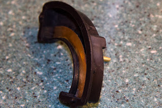
While changing the balancer, I made a discovery about my engine noise this car has always had. See the video.
The rack and pinion unit arrived back from Flaming River tonight, too late to do anything other than check the ends. They are OK... well, at least the one I checked was!
Thursday, January 27, 2011
Vacation: Thursday
- Heater hoses routed and connected - tightened down
- Brake lines from master to combination valve bent up and tightened down
- Bench bled master on the car
- Started bleeding front right - checked connections - tightened loose ones... except forgot about the blockoff plugs on the right side of the master - tightened, re-bled
- Bled left front - no issues
At this point I have some pedal but since I can't bleed the rear circuit yet, I didn't expect much and got about what I expected. Bob even helped me confirm that I've got real pedal, not a repeat of the first go-round with my '58. He turned the rotor while I stepped on the brake to see that the caliper was actually clamping. Awesome! Now I am about as far with the brakes as I can go til I can pull the car out of the garage to bleed the rears, except for some neatening up.
One thing that is a bit alarming is the amount of flex the master/booster has when you step on the pedal. I suppose that is the downside of using the extension bracket. Will have to watch for signs of metal fatigue. Maybe add a brace later on.
I cleaned up the pulleys for the power steering. Wire brushed them and hit them with some black Rust-O-Lium.
I also pulled the Waldron dual exhaust kit I bought some time ago out of the back garage and inventoried the parts to see if the left collector pipe would work any better than the one that was on the car before I started the steering upgrade. I does need some modification and it will have to ride underneath the rack cradle, but it will work much better than the old one.
Wednesday, January 26, 2011
Vacation: Wednesday
- Routed right-front brake hard line through the labyrinth of frame, hoses, engine and attachments like the original to connect up the caliper to the combination valve 45° upper outlet.
Note to self: Next time, make sure of the fitting size to connect to the caliper hose before you route the line and then find yourself having to cut the flare off, put the correct fitting on, and re-flare in the cramped confines of a wheel well. - Bent up and routed the left-front hard line through the inside of the frame, similar to the original, to connect to combo valve bottom outlet.Took two tries as the first tube was too short... I thought it might be but tried it anyway.
That was pretty much it for today... Running hard lines takes time as there are missteps (ahem) and tweaking of the bend, placing clamps, etc. At least I got pictures today.


Tuesday, January 25, 2011
Vacation: Monday & Tuesday
- Heater valve linkage hooked up - rod is all the way in... may need to revisit and add some threads to the rod
- Cleaned up wires under dash - used what I thought was the original brake light power wire - blinkers come on steady when you step on the brake now - needs the old wire back
- Affixed shift quadrant with mounting tape - temporary
- Cut down and affixed the shift pointer with mounting tape - temporary?
- Evaluated neutral/backup switch options - no conclusions yet - attempting to modify the one supplied to work with my HydraMatic by eliminating the 2nd and 3rd start positions and makeing new backup terminals
- Right caliper mounted with hose
- Bent up hard brake line for right front caliper
- Adapted rear brake 1/4" line, bent to point up by the firewall, cut and flared
- Attached 10 lb residual valve a 1/4" line inlet
- Mounted combination valve to frame on the inner side, a few inches back from the steering cradle - there is a raised part on the frame there where the two rails become one boxed section
- Cut and attached intermediate hard line between combo valve and rear residual valve - so the rears are plumbed to the valve now
Didn't seem like I accomplished that much but I guess I did.
Sunday, January 23, 2011
Booster Mounted
The power booster is now bolted onto the firewall brackets, all ready to accept the master. Meanwhile, I was going to order an electronic heater valve from OldAir but figured I could do a little finagling to get the old one relocated so it was still usable. It's mounted on the firewall and I'll have to hook up the linkage tomorrow.


Saturday, January 22, 2011
Some Brake Progress
Turns out buying the power brake pedal conversion kit from Ecklers was very smart. It worked perfectly. I chose to cut off the old smaller pedal pad since I had screwed it up a lot already anyway and I wanted the pedal to sit a bit further away. I tack welded it, tested it for fit and angle, then welded it down tight. Finally the pedal is finished!

You can see that part of the swing pedal upper bracket that I cut off behind the assembly there. I used part of it later on the booster bracket. Nothing goes to waste! I want to buy the correct switch for the stop light now. I have one for a '73 Cad in there now and it doesn't work that well. But everything else is good.
So next I started working on the brackets I bought to mount the booster. Turns out this was also a very smart thing to buy, as I can stand the booster out aways from that uneven firewall and at the same time, the bracket angles the booster so the rod points to the lower hole in the brake pedal arm instead of the original hole. Much better!


You can see I had some fun with the left bracket, as that is the wickedest part of the firewall. I ran out of time and I need a longer bolt for this hole so I'll be making a hardware store run in the morning. Now what am I going to cover the old holes with when I go to finish up this panel... ?
Monday, January 17, 2011
Parts ordered. I decided to try one of the mounting bracket kits sold on eBay to mount a modern booster on a '55 Chevy.
What the heck. I figured after 55 years, the old Chevy pedal assembly needed a new bumper.
I was trying to make this and made a mess so now I'll cut off the crap I did over the weekend and put this nice pedal on and keep my Pontiac pedal all together.
 |
| From eBay |
What the heck. I figured after 55 years, the old Chevy pedal assembly needed a new bumper.
 |
| From Eckler's |
I was trying to make this and made a mess so now I'll cut off the crap I did over the weekend and put this nice pedal on and keep my Pontiac pedal all together.
 |
| From Eckler's |
Sunday, January 16, 2011
Pedal Pushback
Looks like the master cylinder and booster I will be using is from the Jegs kit #555-631090 Universal Firewall mount Power Brake Pedal Conversion Kit. I bought it to use on the '49er, but I need parts of it for this car. It seems the spot I'm going to be mounting the pedal in will put the booster closer to the engine than will allow for a big booster like the 2000 Sierra one I bought to use with this car originally.


As I've been working to mount the pedal, I've come to realize that the firewall is a problem because it's not flat. I'll need to come up with some kind of standoff to push the booster out to the part of the firewall that is closest to the engine. Then the plate the pedal assembly is attached to will have to mount on the part that is furthest. Not the best. Also I'm not happy with the pedal pad I mounted yesterday. I think I want to cut the original pad from the pedal arm, make a new one from plate and mount it lower and sightly left of the original.


As I've been working to mount the pedal, I've come to realize that the firewall is a problem because it's not flat. I'll need to come up with some kind of standoff to push the booster out to the part of the firewall that is closest to the engine. Then the plate the pedal assembly is attached to will have to mount on the part that is furthest. Not the best. Also I'm not happy with the pedal pad I mounted yesterday. I think I want to cut the original pad from the pedal arm, make a new one from plate and mount it lower and sightly left of the original.
Saturday, January 15, 2011
Brake Pedal Progress
Today I pulled the defroster plenum... unfortunately had to cut it. But with that gone I had room to start test fitting brake pedals. The Cadillac one I had will not work because it needs to mount too high and won't clear the cowl. I have the hot-rod one from Jegs and it could be made to work. But I think I like the '55 Chevy pedal best. I cut off the part that attaches to the dash as it doesn't mesh up with the Pontiac dash well anyway. Then I had a universal booster mounting plate I got from CPP awhile back and I cut that to shape and welded the Chevy pedal assembly to it. I drilled holes in the Chevy pedal pad plate to mount the Pontiac pedal pad. Not sure of this arrangement.


Gorgeous 80° day here today. Sunny and just wonderful for chasing away the blues and the last cold sniffles I had. :-)


Gorgeous 80° day here today. Sunny and just wonderful for chasing away the blues and the last cold sniffles I had. :-)
Thursday, January 13, 2011
Send It Back
So at 7-something this morning, I was on the phone to Kevin at Flaming River Tech Support. Nice guy. Had a hard time believing the problem I was having, but when I told him the jamb nut they supplied fit but not the rack end, he knew something was not right. He gave me an RMA number to return the rack for service and I went out and pulled it off right away. Just took the 4 bolts out that hold it to the cradle and released the steering linkage. Pretty simple. Took the rack over to my local pack and ship and it's happily on it's way back to Ohio. Should get there next Wednesday.
Note to self: When you put the rack back in, put the upper right cradle bolt in first, then swing the rack up to meet the steering linkage and reseat the u-joint on the rack input shaft before putting the other bolts in. With all 4 bolts back in loosely, push rack up as high as it will go before tightening the bolts down. Then tighten down the steering linkage to the input shaft.
Note to self: When you put the rack back in, put the upper right cradle bolt in first, then swing the rack up to meet the steering linkage and reseat the u-joint on the rack input shaft before putting the other bolts in. With all 4 bolts back in loosely, push rack up as high as it will go before tightening the bolts down. Then tighten down the steering linkage to the input shaft.
Wednesday, January 12, 2011
It Don't Fit!
So the first of the two '68/'69 Camaro tie rod ends arrived tonight. The first thing I did was try on the jamb nut supplied by Flaming River in the hardware kit. It fit perfectly! Then I put the end of the tie rod up to the rack tube and... drum roll... It slipped in and out without threading... just slopping around loose like. BOO!!! Two thumbs down for Flaming River's Tech support. It seems the next size up is probably 11/16" and that seems like it's a Mustang part, not a Camaro part. Could it be the wrong rack was included in the kit? I'm going to be calling them in the morning.
Ugh!
Monday, January 10, 2011
Flaming River Tech Support
I had posted a question on Flaming River's Facebook page over the weekend and this morning got a reply.
They say to use '68-'69 Camaro outer tie rod ends, Moog part number ES381RL. I looked up the specs on this item and the rod thread dimensions are .625-18R... that's a right handed thread. I have been dead certain that the threads on the rack are LEFT handed. I ordered the parts from Amazon but called the FR tech support guy to be sure. He swears there are no racks they make with left handed threaded tubes. OK. I am perfectly willing to be known as an idiot, and it would certainly explain why the jamb nut they provide is a common right hand thread. I am very willing to believe I completely screwed this up... I've been sick, the weather's been a mess, I'm busy jumping through hoops to get something to fit a car it wasn't designed for, as well as my normal, shoot-from-the-hip-ask-questions-later style of doing things. You're supposed to get smarter and/or wiser as you get older, but I think I do the reverse...
Still, the instructions don't mention having to buy tie rod ends or what kind are needed. In fact the kit is sold as absolutely complete, no need to buy anything except the hoses for the pump. True, the answer is just a phone call away... unless it's the weekend. And still no mention of how to adjust toe-in... do you have to pickle fork the steering arms each time? It's really not a big deal if you do, since you shouldn't have to do it often. But it would be nice to have it spelled out. (Feeling crabby this morning now.)
They did get back to me later today on Facebook about the toe-in adjustment.
"The small clamp on the boot must be removed, and then the sleeve/inner end can be turned either way. There is a ball socket assembly underneath the boot. If you have any other questions, I would recommend calling us at 1-800-648-8022 for instant tech support, and one of our technicians can answer any other questions you might have."
Sunday, January 9, 2011
Turn Signals
Today was spent sorting out the turn signal wiring. The new column came with a male GM flat connector and a kit to make up the female half. I used the connectors from a spare column I had on hand so as to not cut anything from my original column. With those, I made up a little adapter harness that connects between the factory connectors on the car and the flat connector on the column. And best of all, everything works! It took most of the day because I had to translate the color code of the wires, scrounge the connectors, pull them apart, solder in new wire, solder in the pins for the flat, and test everything.
 The white wire for the brake light is a passthrough for the brake feed. Has no power on it unless the brake pedal switch is closed. The turn signal power wire is from the flasher. So that power signal "blinks".
I may add the hazard kit later on. It would be nice to have.

I may add the hazard kit later on. It would be nice to have.
Saturday, January 8, 2011
Tie Rod Ends
OK this is getting frustrating. I got the new outer tie-rod ends from Eckler's today and of course, there is no way they will work. I thought perhaps the inner rod would be what was needed. So I called Cooper and he had a pair. Went and got them and... of course, same thing. the end just slides in and out of the end of the rack. What *looks* like it might fit is the inner tie rod end of the Pontiac, but of course that has the wrong end on it to connect to the steering arm. I called Jegs technical support since they are who I bought the kit from. They had no idea and they tried to reach Flaming River but no one was there as it's the weekend. The Flaming River web site is down today too. I searched every bit of packaging material from the box for something missing but no luck.I posted a message on the Flaming River Facebook page too... no answer. OK. I'm stuck til Monday I guess.
So meanwhile, I started looking at the power steering pump. It is much smaller than the orignal and I thought I was going to use the original mount but it turns out I am not. I can make a simple plate adapter that will bolt where the original went and let me use the mount Flaming River supplied. One thing, a fan belt was supposed to be included in the package and it's not here... not that I could use it anyway. I will need to dig out the crank and fan pulleys I got from eBay now.
So meanwhile, I started looking at the power steering pump. It is much smaller than the orignal and I thought I was going to use the original mount but it turns out I am not. I can make a simple plate adapter that will bolt where the original went and let me use the mount Flaming River supplied. One thing, a fan belt was supposed to be included in the package and it's not here... not that I could use it anyway. I will need to dig out the crank and fan pulleys I got from eBay now.
Friday, January 7, 2011
Steering Linkage
Started on the steering joints and rods. I used a 3/4" dowel as suggested by the documentation for the kit. But with a dowel, you can't actually rotate the linkage much. So I got the lengths of rod cut but when I assembled, I found the middle u-joint is binding. Too steep of an angle. I don't know if there is a "wrong" way to put this linkage together, but I had to figure out a way to decrease the angle a little. So I reversed the setup I originally planned based on the photoshopped image I got out of the PDF instructions. With the lollipop where it was, I could not decrease the angle enough without running out of the longer shaft I had already cut and without making the angle of the lollipop too extreme. I needed to straighten the bracket that holds the lollipop a little to decrease that angle. I also shimmed it out about a half-inch from the frame with washers. That plus putting the middle u-joint above the lollipop made the angle work out pretty well. Of course, before I finalized the steering rods, I had to get the shifter link in place. With all the holes that thing has to adjust it, none would line up. I had to drill four holes between the existing holes and siamese them to give me a bit of adjustment once on the column. I *think* I have it set so that the upper detente-locked position of the shift lever is neutral on the trans. I won't be able to really tell how it works until I can fire up the engine and try it.

With the linkages set, I snugged down the column and turned to addressing the levers and wheel. For the turn signal lever, I made some modifications to the original to make it work with the new column by flattening the top and bottom of the round lever end, then spot welding a tiny bit of flat metal to the bottom to fill the wider slot on the new switch. And I also had to drill out the hole for the screw a little too. Not sure it was all worth it over using the Flaming River one... but since that one is shorter for smaller wheels, it probably is.

So that leaves the horn.The Flaming River horn contact needs a male spade lug to connect to. The simplest first attempt is to solder a lug onto the correct part of the horn ring. I know the joint looks dicey, but it had plenty of heat and flux, so maybe it will hold. If not, the next attempt will include drilling a tiny hole for a screw. It can't protrude far though, as the foam ring behind the horn assembly mustn't be damaged by it.

Subscribe to:
Posts (Atom)